 MIDAS Hand
1. Prepare the 6 types of screws, pins, and 2 types of bearings.
Build guide
Assembly
Step-by-step build reference for preparing the parts, setting Dynamixel IDs, assembling fingers and thumb, routing tactile sensors, and closing the palm.
Assembly GuideAssembly Guide
Each build section includes its own video slot, reference images, and step notes.
01 Prepare Parts Hardware, prints, electronics, tools
2. Prepare all 3D-printed (3DP) parts.
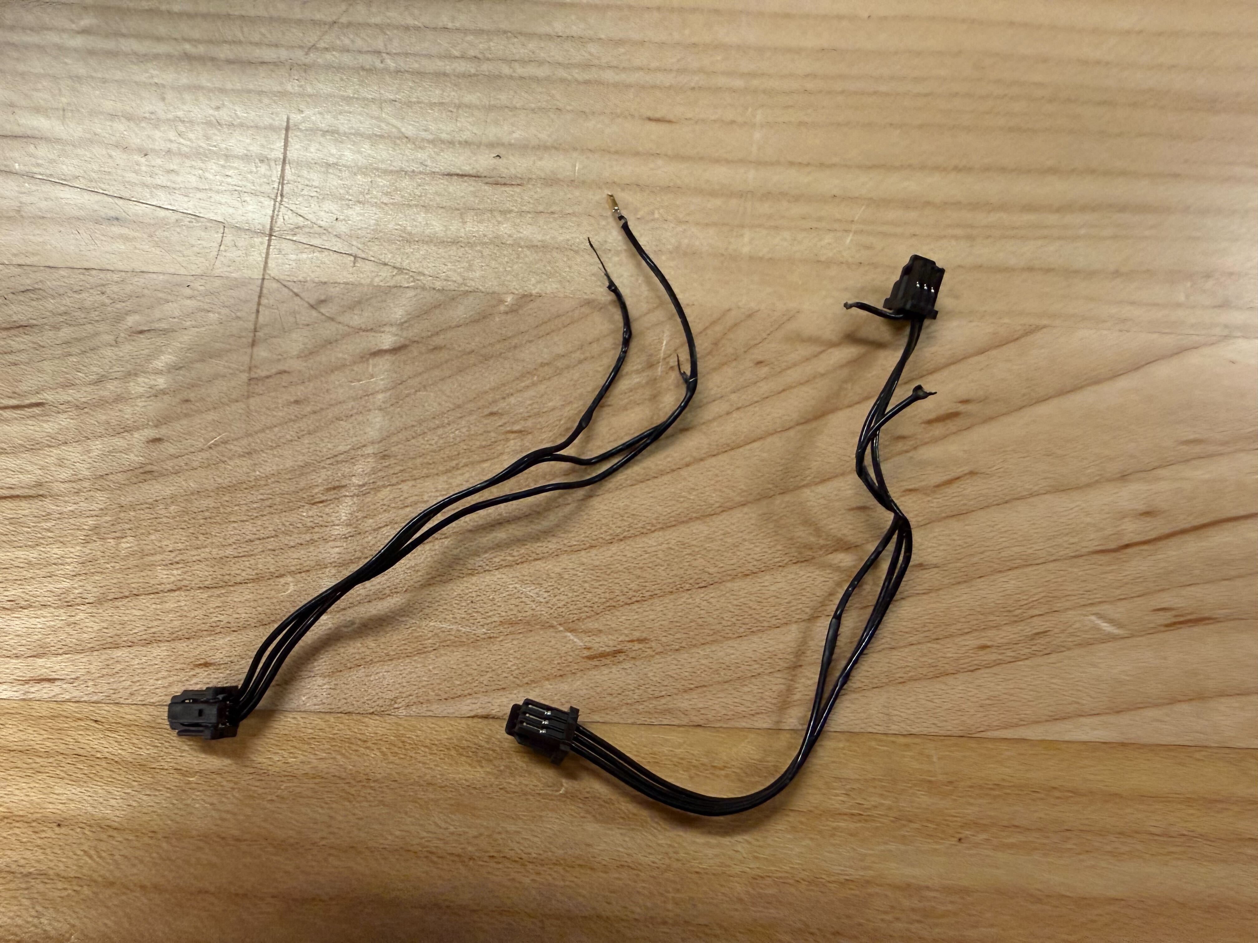
3. Prepare the motors and wires.
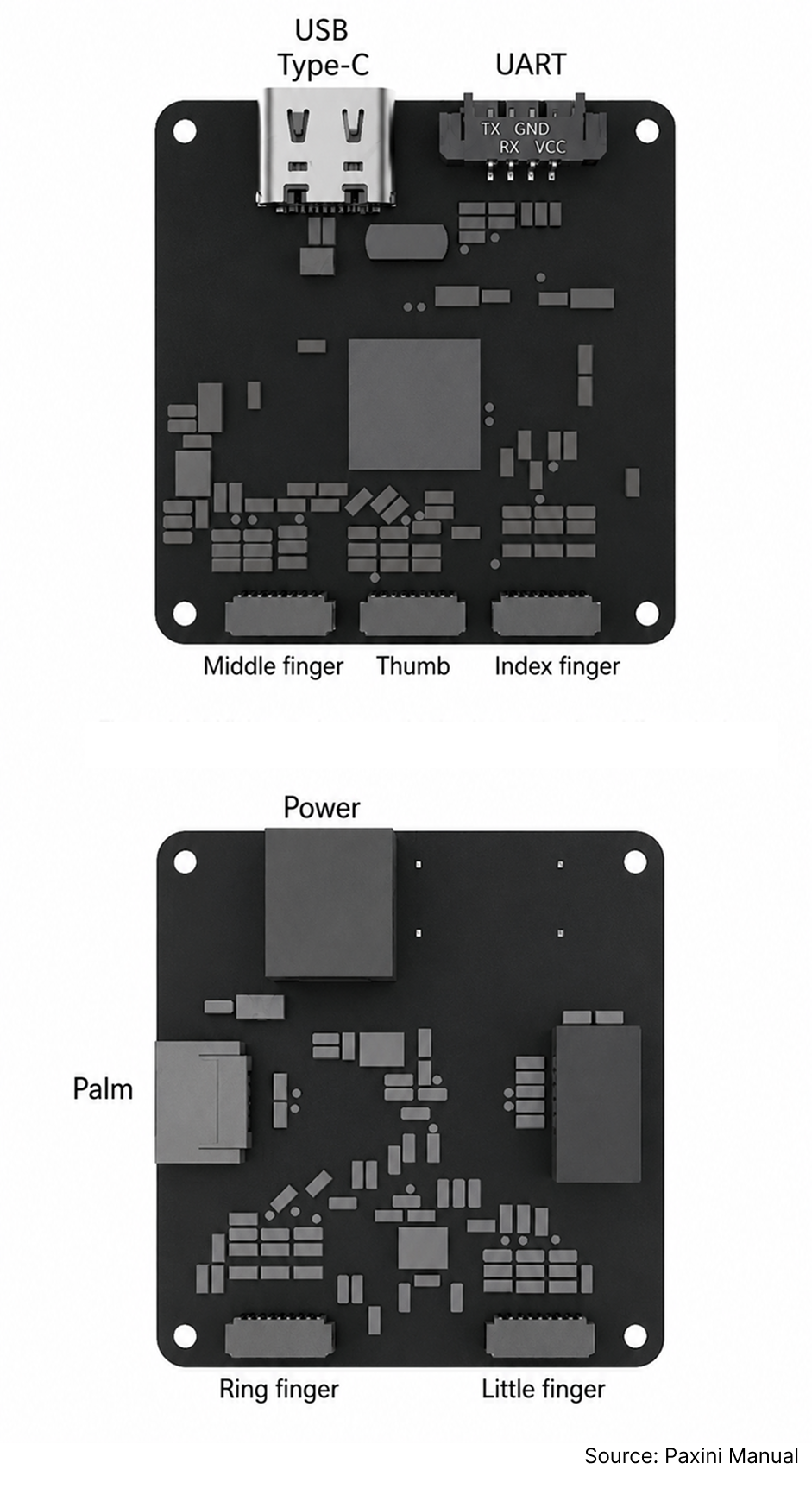
4. Prepare the boards, including the U2D2 power hub and Dynamixel collection board.
5. Prepare the tactile sensors and their wires.
6. Gather necessary tools: tweezers, a JIG, and a screwdriver.
7. If press fitting bearings, pins cause problem, refer to tolerancing guide
02 Set Motor ID Dynamixel setup and neutral alignment
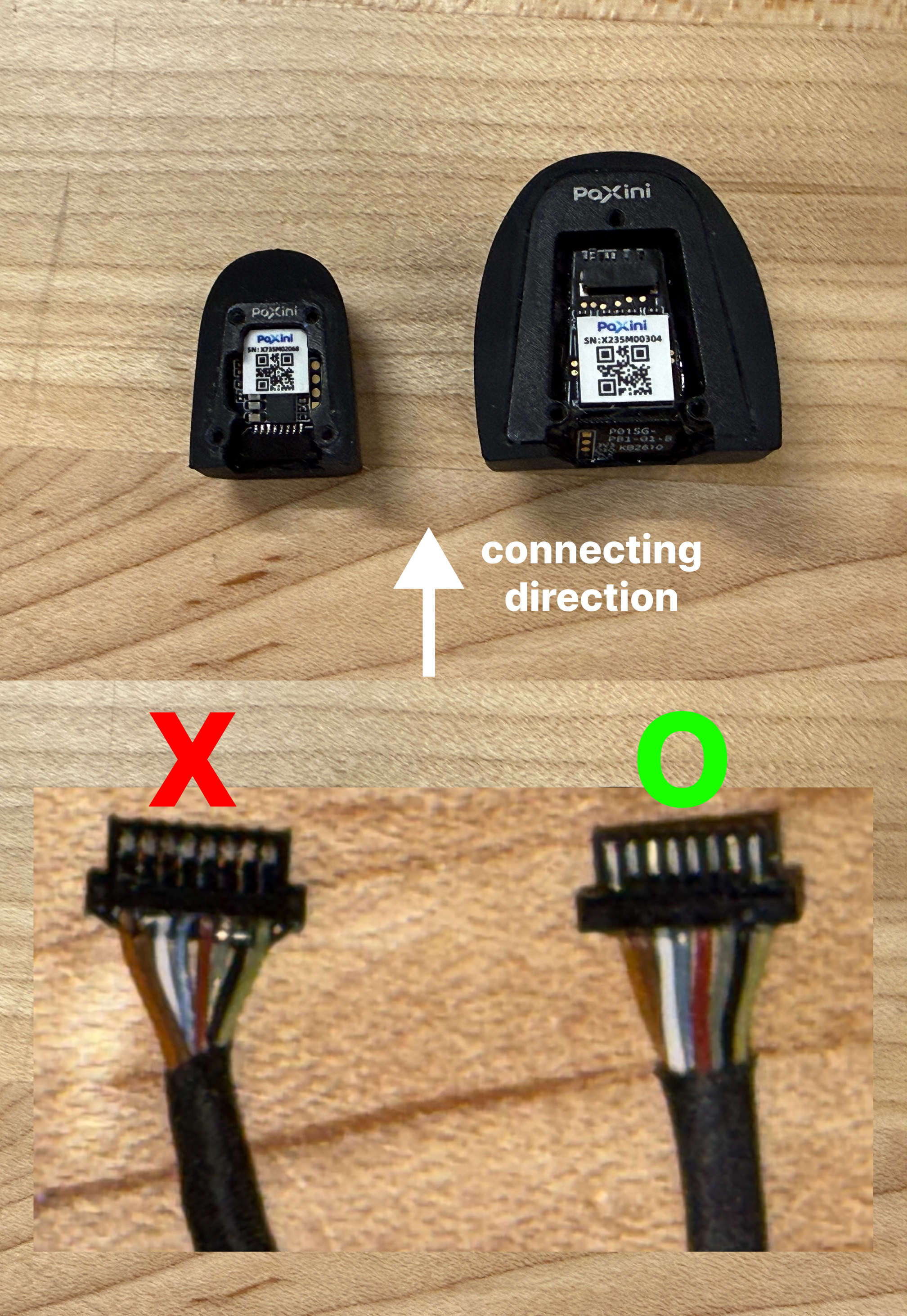
1. Unscrew the Dynamixel to connect the wires.

2. Connect the wires.
3. Warning: Always push the buttons when pulling to prevent wire disconnection.
4. Ensure the wire connection for the board matches the reference image.
5. Turn on the Dynamixel Wizard software. Set the Protocol to 2.0, port to usbserial, and baud rate to 1,000,000
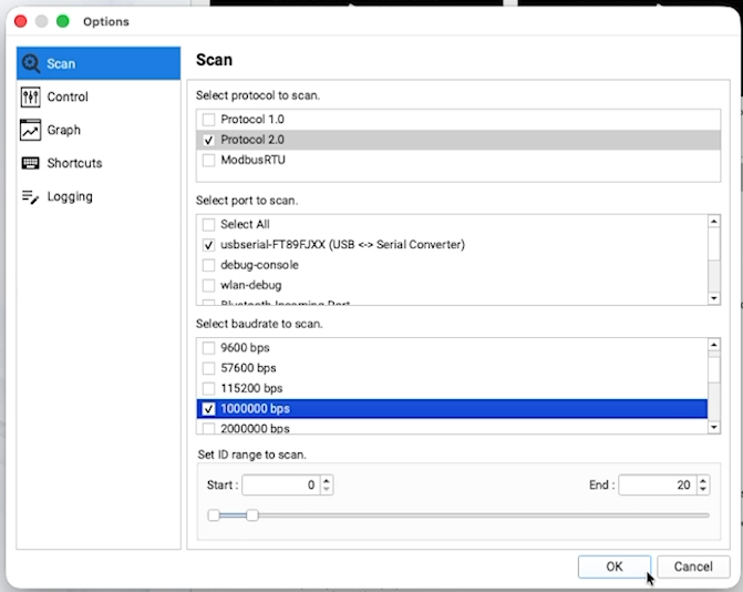
6. Set motor ID and change baud rate to 4,000,000.
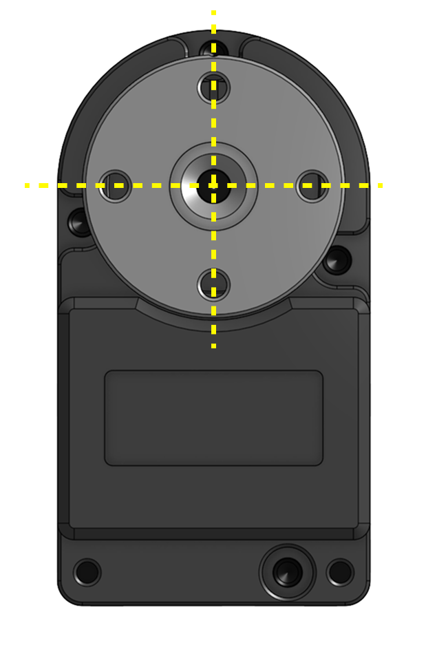
7. Verify that the horn is positioned at exactly 180 degrees when correctly connected.
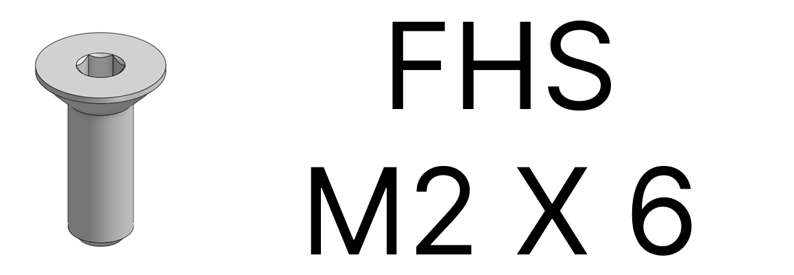
8. Assemble the servo horn using an FHS M2x6 screw from the Dynamixel kit.
9. Repeat this process for the other motors, assigning IDs from 0 to 12 as shown in the attached image.
.png)
03 Index, Middle, and Ring Finger Assembly MCP, DIP linkage, bearings, pins
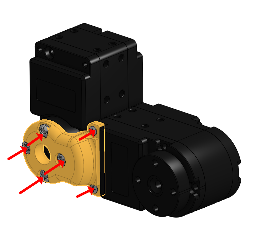
1. Assemble Motor 5 to the 3D printed MCP part
2. Assemble Motor 6 to the 3D printed MCP part, ensuring the encoder value is 180 degrees and the motor aligns perfectly with the 3DP parts.
3. Bolt in the MCP 3D printed parts Guide the wires through the designated paths in the 3D-printed parts to avoid pinching.
4. Leave a margin of wire length between Motor 5 and Motor 6, storing the excess wire inside Motor 5.
5. Be careful not to pinch wires inside the motor to prevent damage or short circuits.
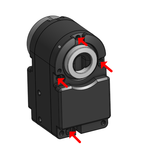
6. Screw to close the motor case
7. Connect Motor 4 and Motor 5.
8. Organize the wiring neatly between Motor 4 and Motor 5.
9. Connect Motor 4 and Motor 5 again, double-checking the servo horn direction and ensuring the part alignment remains at 180 degrees.

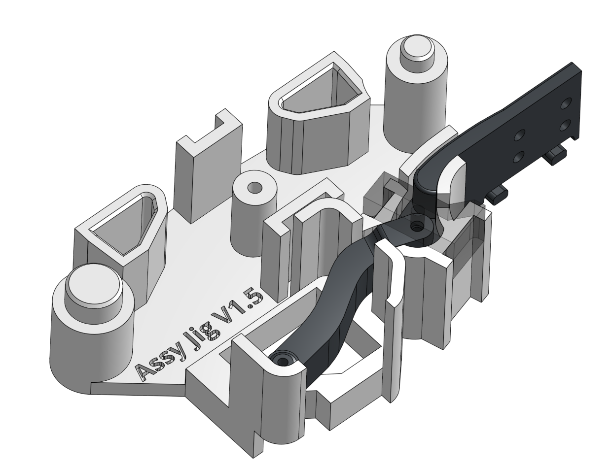
10. Prepare the JIG for assembly.
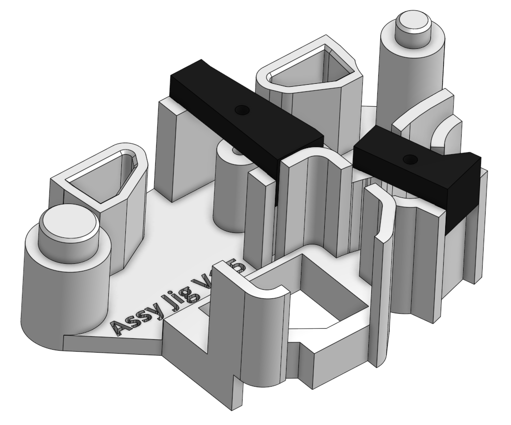
11. Place two bearings into the designated 3D-printed part.
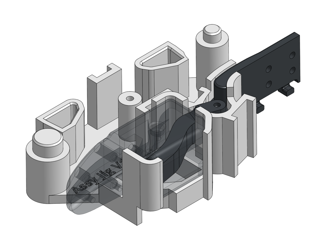
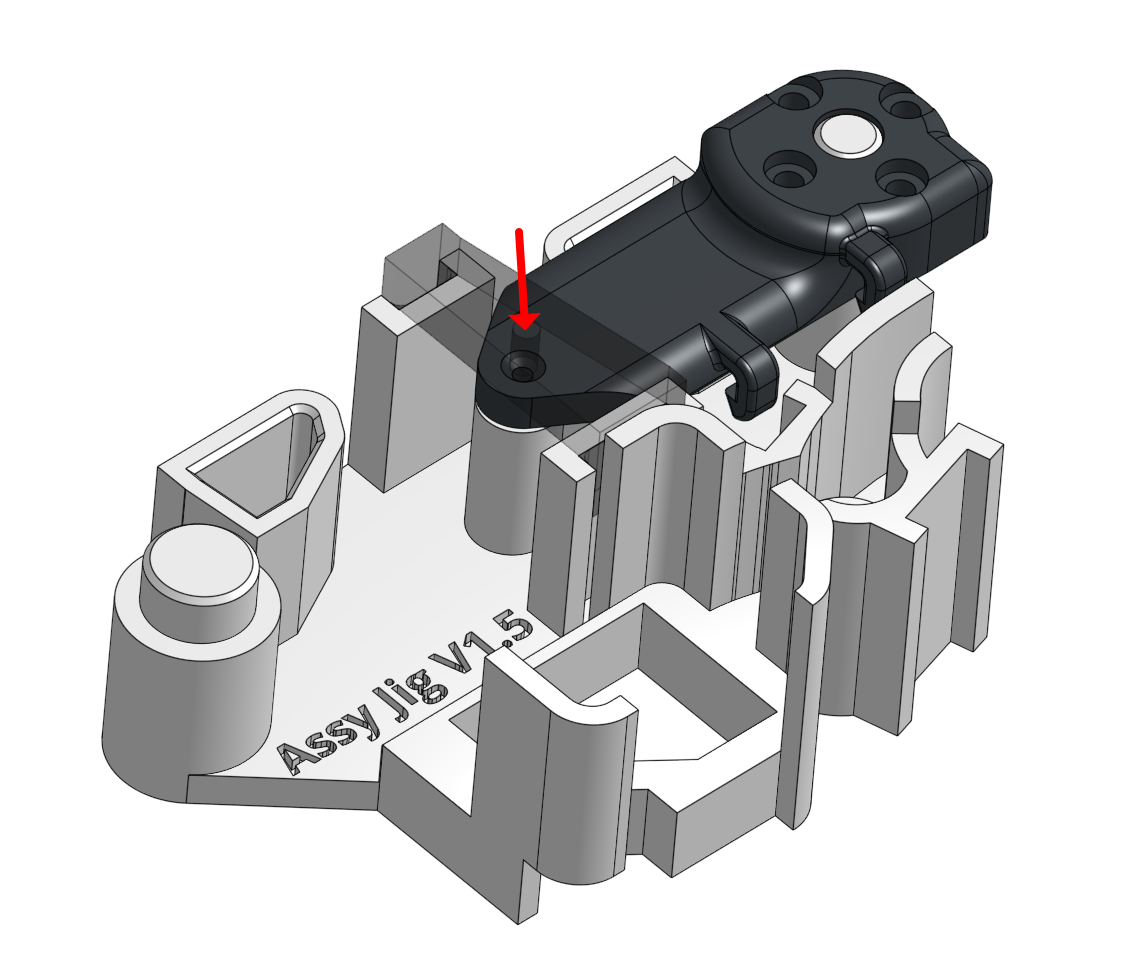
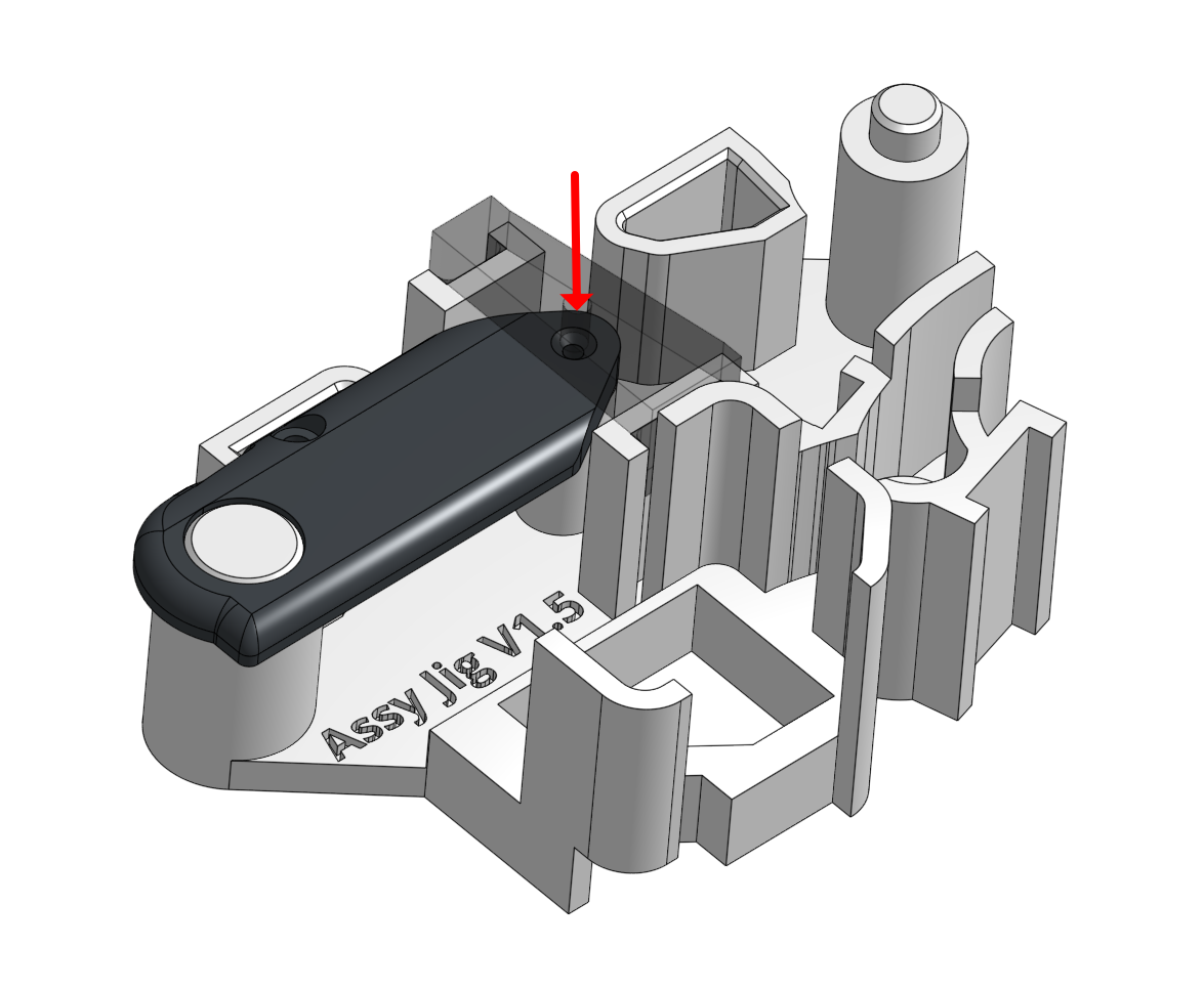
12. Assemble the two parts as shown in the picture and place them into the JIG.
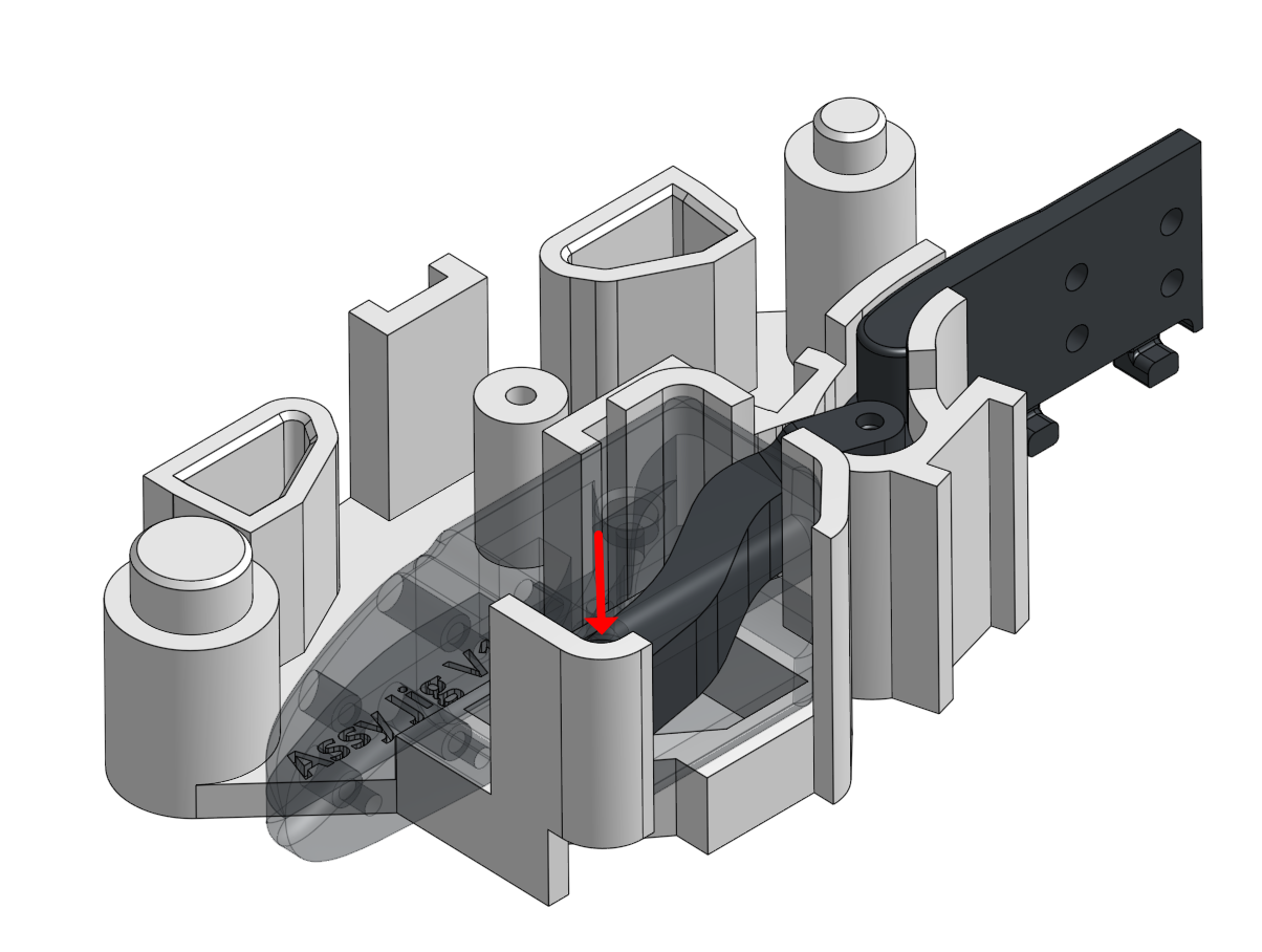
13. Put on the JIG cover and push the first pin in.
14. Remove the cover and push the pin further down
15. Put back the cover and use a second pin to push the first pin deeper into place
16. Put back the cover and use a second pin to push the first pin deeper into place then remove the second pin
17. Verify that the assembled joint has minimal friction and moves smoothly
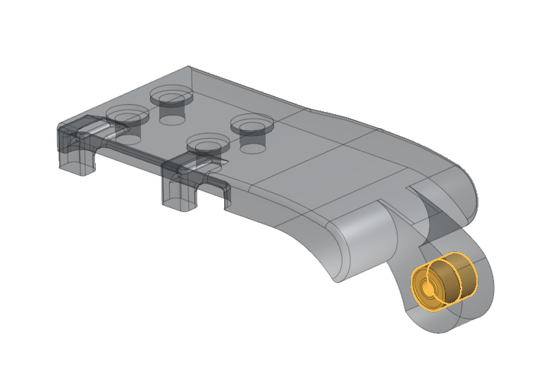
18. Place 4 bearings into the DIP joint.
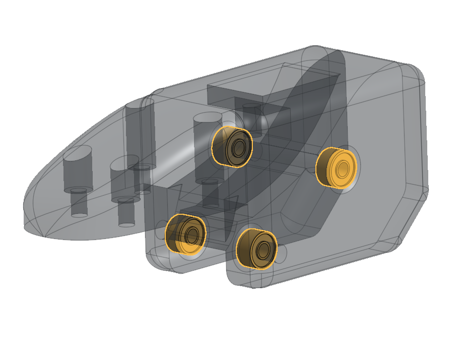
19. Align the DIP, Linkage, and DIP Link 3D-printed parts, then place them into the JIG
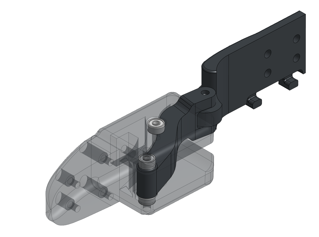
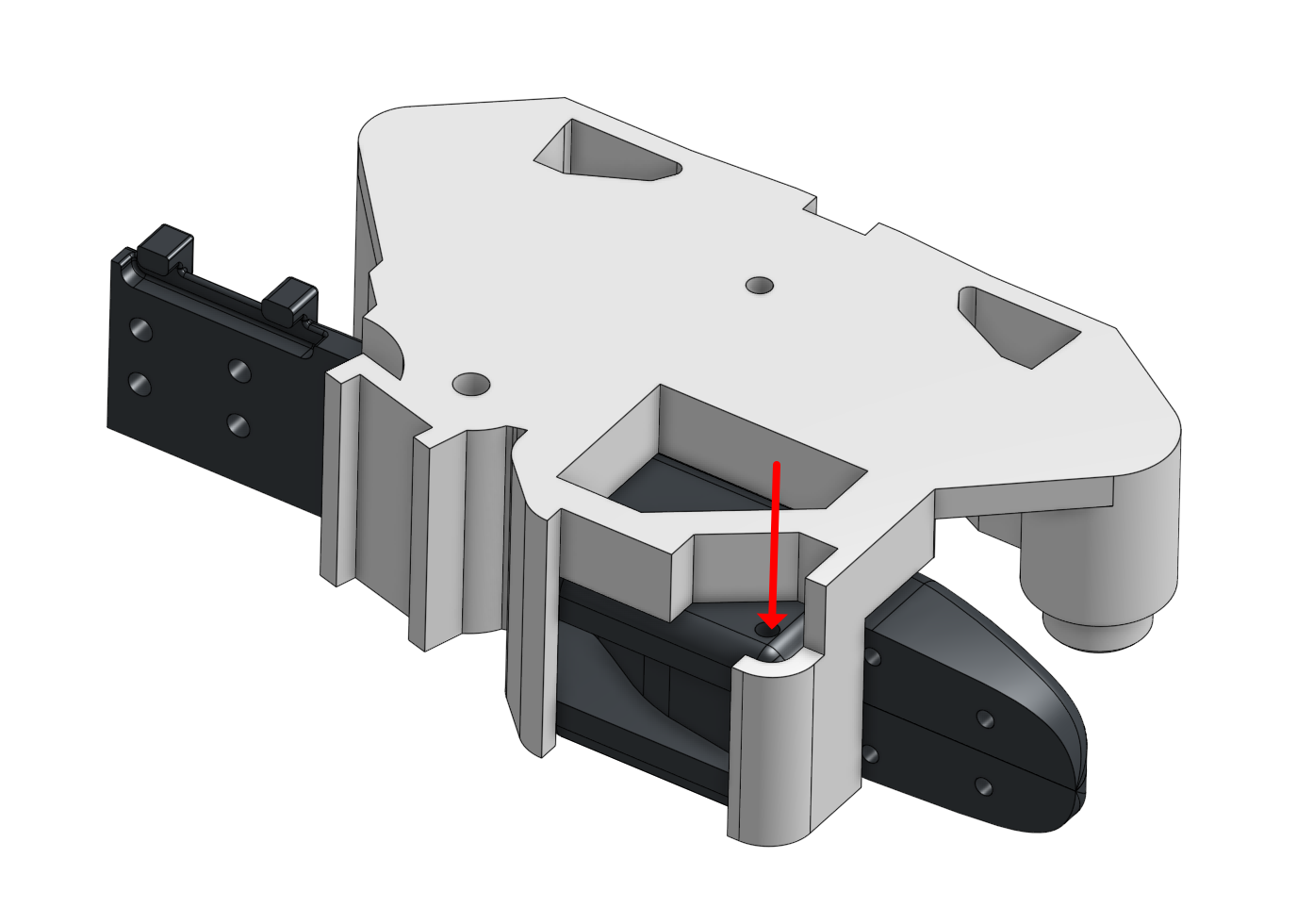
20. Insert the pin
21. Flip the JIG over and push the pin in from the other sid
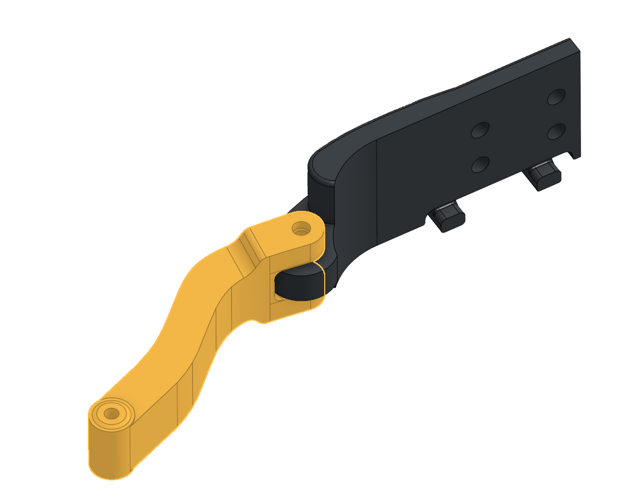
22. Place the first side phalange piece onto the JIG, put on the cover, and push the pin
23. Remove the cover and push the pin in
24. Repeat the process for the second side phalange piece
25. Assemble the DIP Link to Motor 4
26. Assemble both side phalanges to Motor 4, verifying the encoder is at 180 degrees and all 3D printed parts align correctly
27. Tighten the screws connecting both side phalange parts.

28. Verify that the assembled joint has minimal friction and moves smoothly.
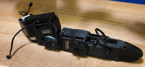
04 Thumb Assembly Thumb motors, wire margin, alignment
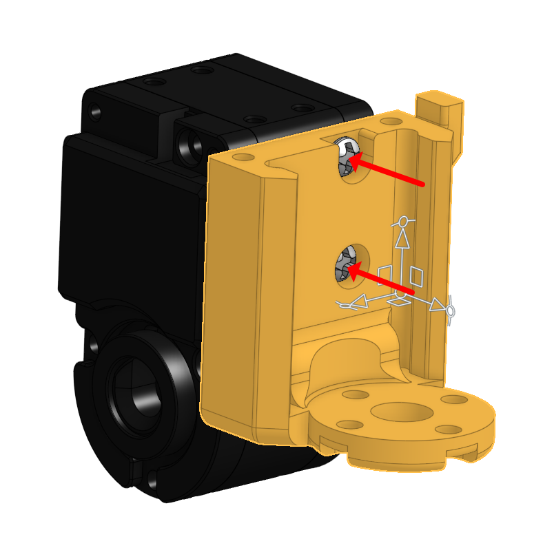
1. Assemble the DIP to Motor 0, making sure the encoder is at 180 degrees and the parts are aligned
2. Assemble the 3D-printed parts to Motor 1 and 0, again ensuring the encoder is at 180 degrees and aligned.
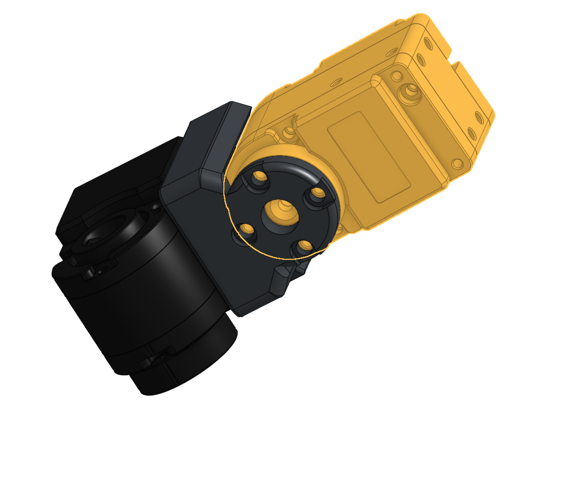
3. Align Motor 0 and Motor 1, keeping the wire length appropriate for the position.
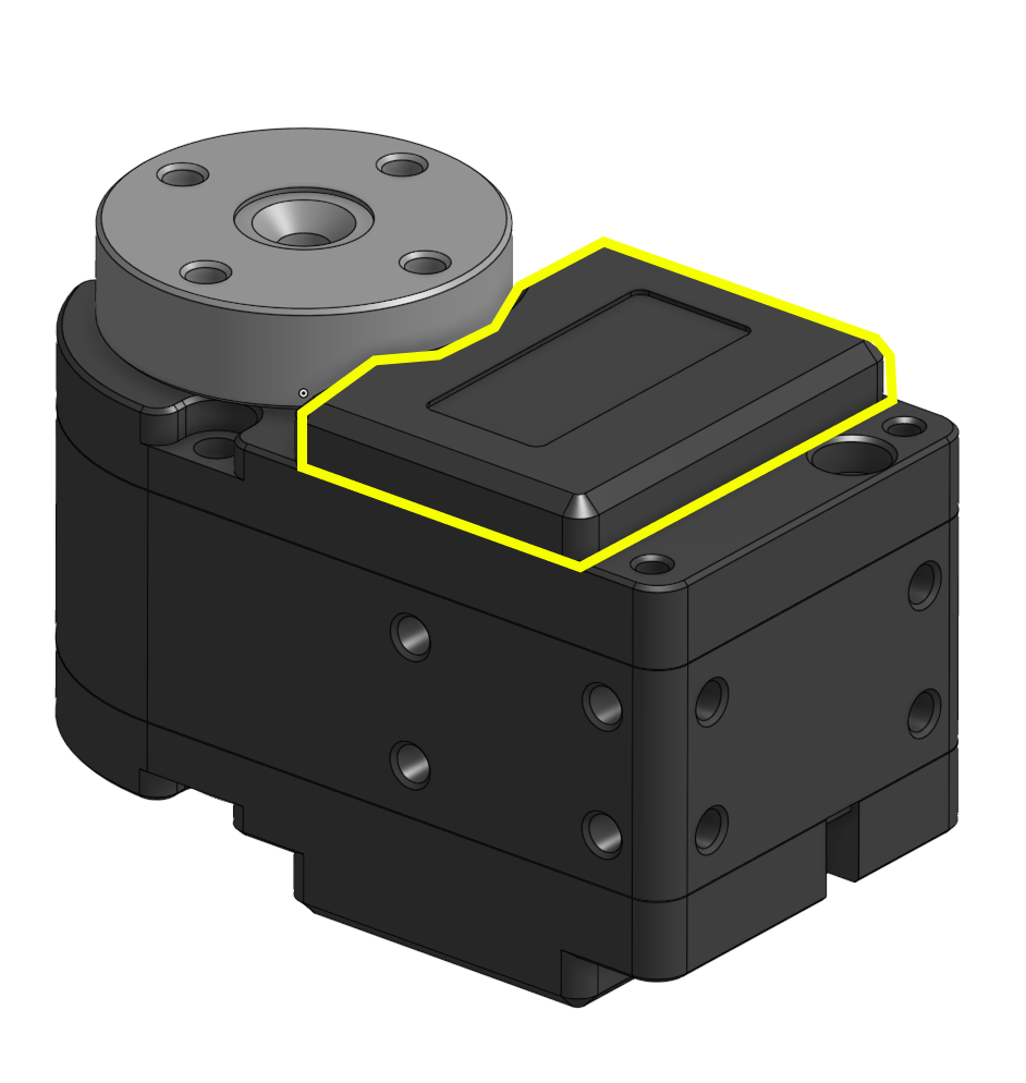
4. Organize all margin wires neatly into the Motor 0 housing, keeping cables within the highlighted area and avoiding pinches.

5. Route the wire coming from Motor 1 through the designated wire hole in the 3D-printed parts.
6. Assemble the respective part with Motor 1.
7. Leave about an inch of wire between Motor 1 and Motor 2, storing the remaining wire inside Motor 2.
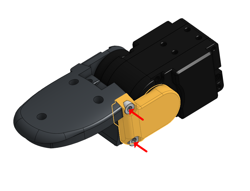
8. Assemble the respective part with Motor 2.
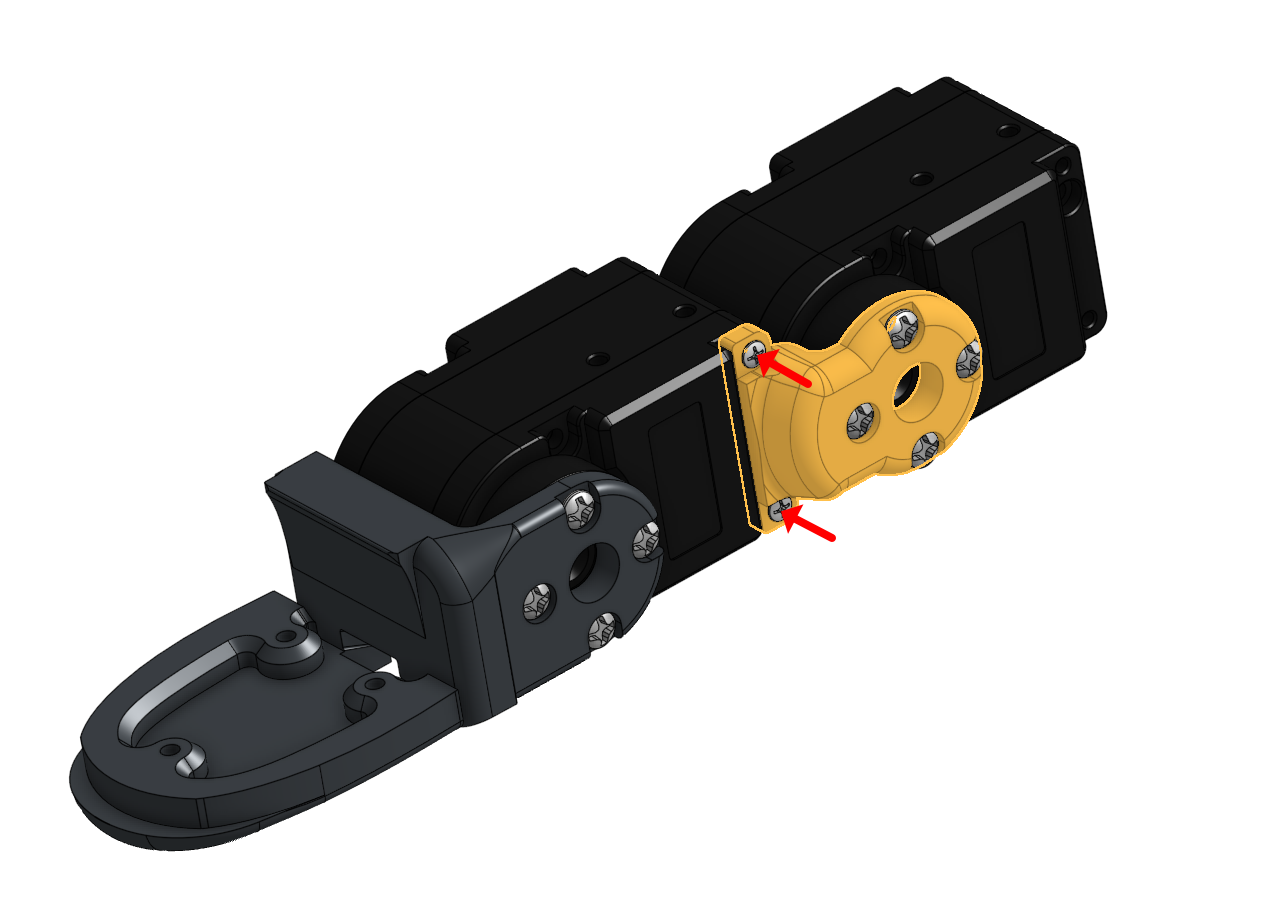
9. For the connection between Motor 2 and Motor 3, store the margin wire length inside Motor 3.
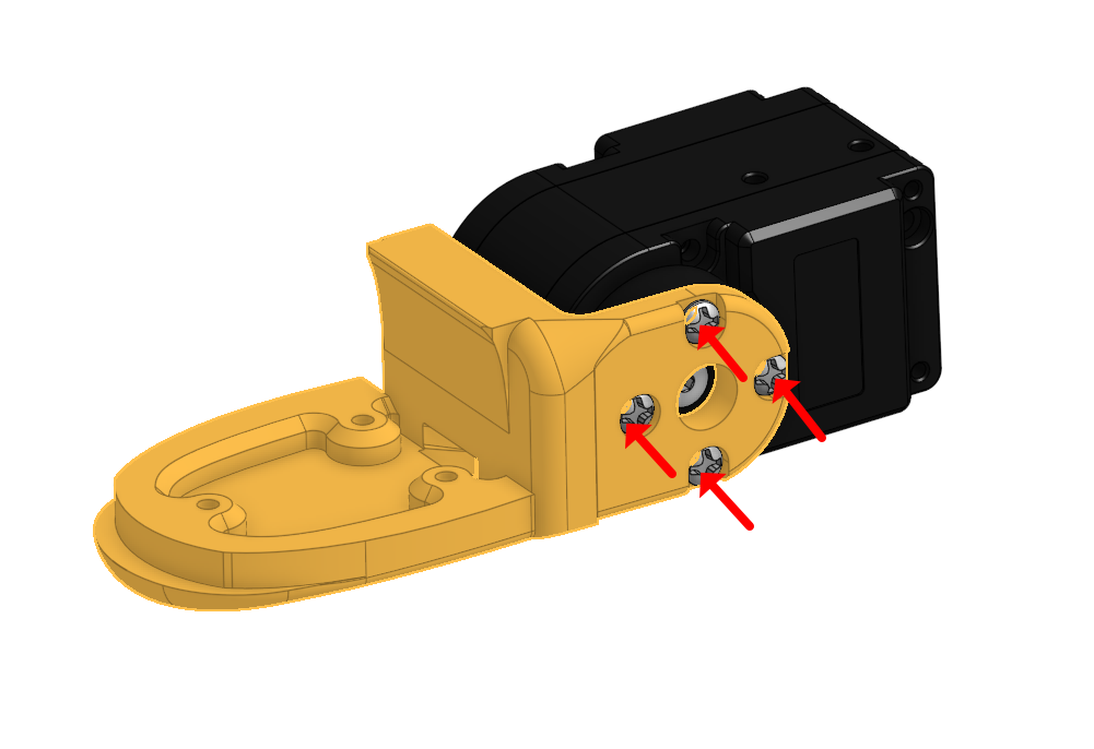
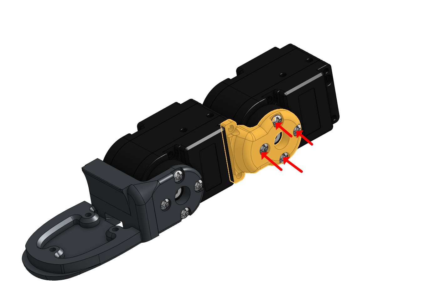
10. Align Motor 2 and Motor 3, confirming the encoder value is at 180 degrees and parts match the picture
05 Tactile Sensor Assembly Finger and thumb tactile routing
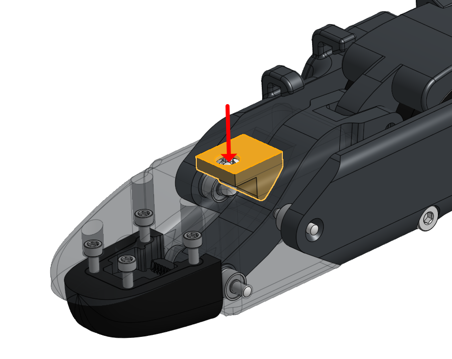
1. Connect the wire to the sensor, route it through the designated path, and screw in the sensor to the DIP part

2. Simply push the wires into the hooks located on the side phalanges.
3. Unscrew the DIP Link and MCP parts to utilize the internal wire guides.
4. Organize the tactile wires on the fingers by anchoring the wire onto the DIP
5. Bend the fingers through their full range of motion to ensure enough slack margin for the tactile wires.
6. Connect the wire to the sensor, route it through the designated path, and screw in the sensor to the DIP part
7. To organize the thumb's tactile wires, add an anchor point on the DIP.
8. Screw in the designated wire guides for the thumb.
9. Bend the thumb through its full range of motion to secure enough wire margin
06 Palm Top and Cover Assembly Final hand closure and board mounting
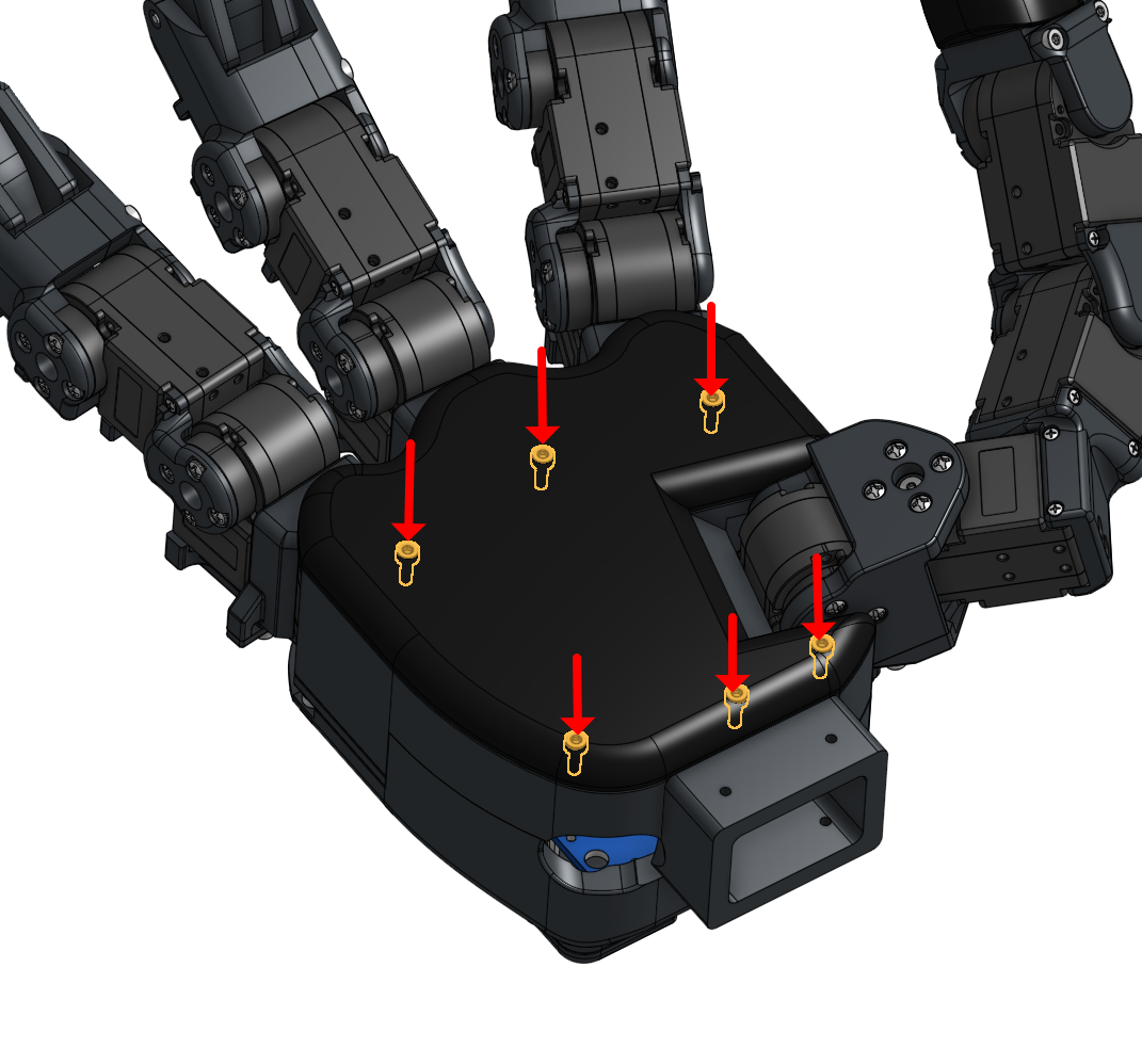
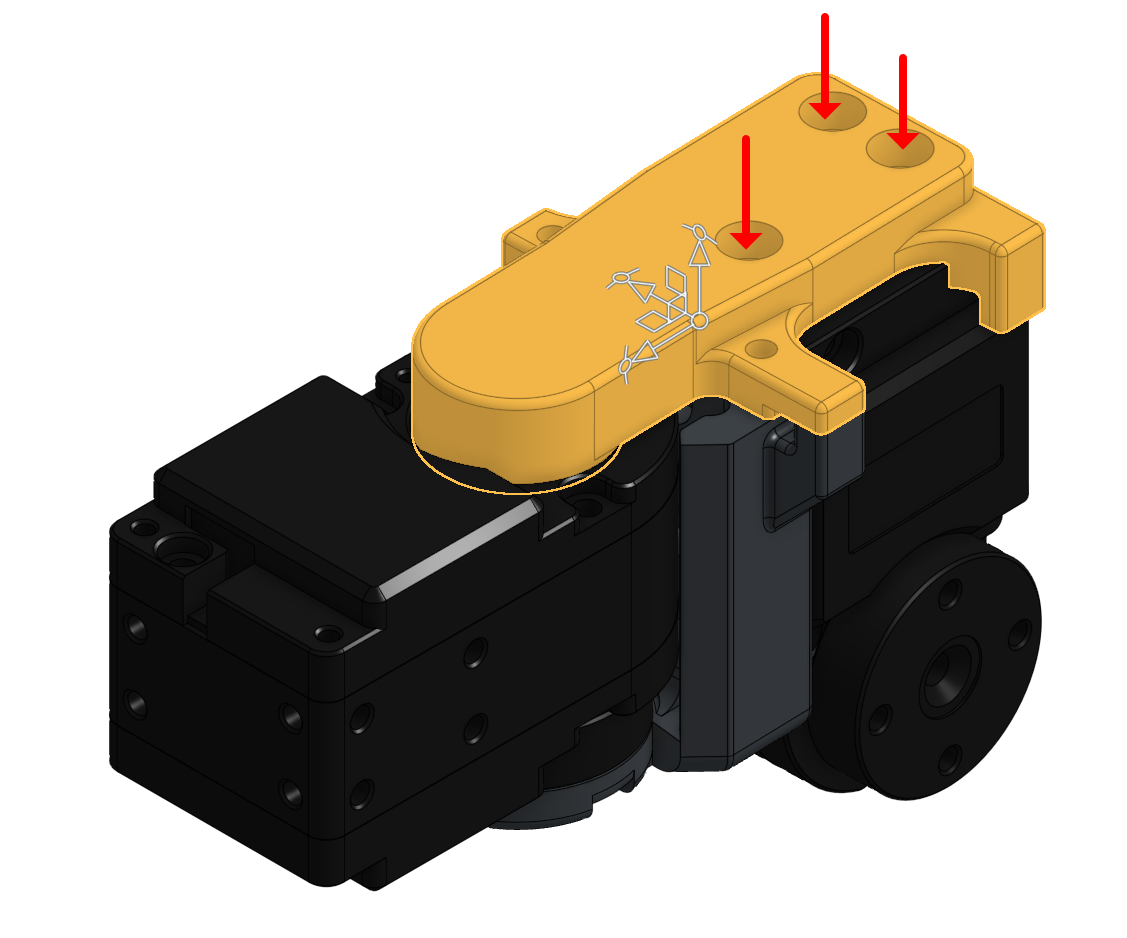
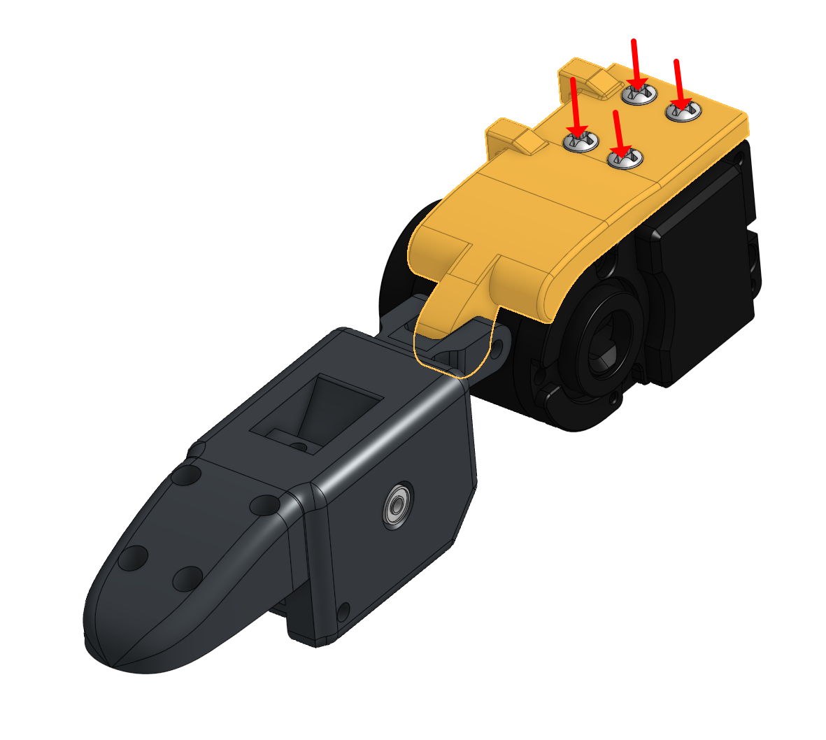
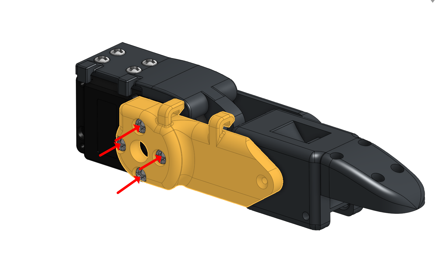
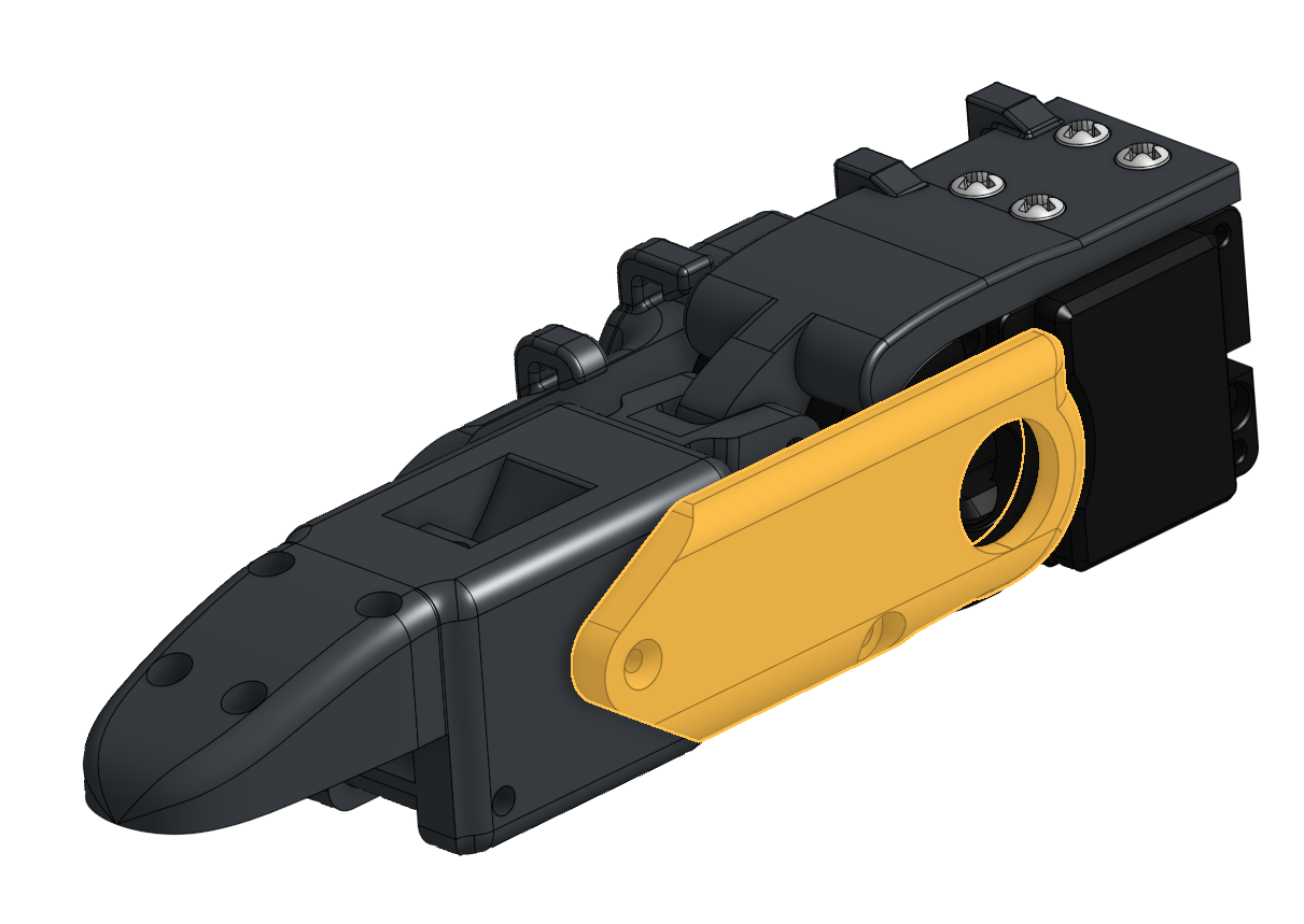
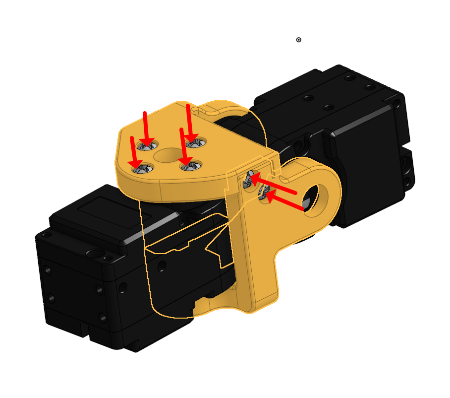
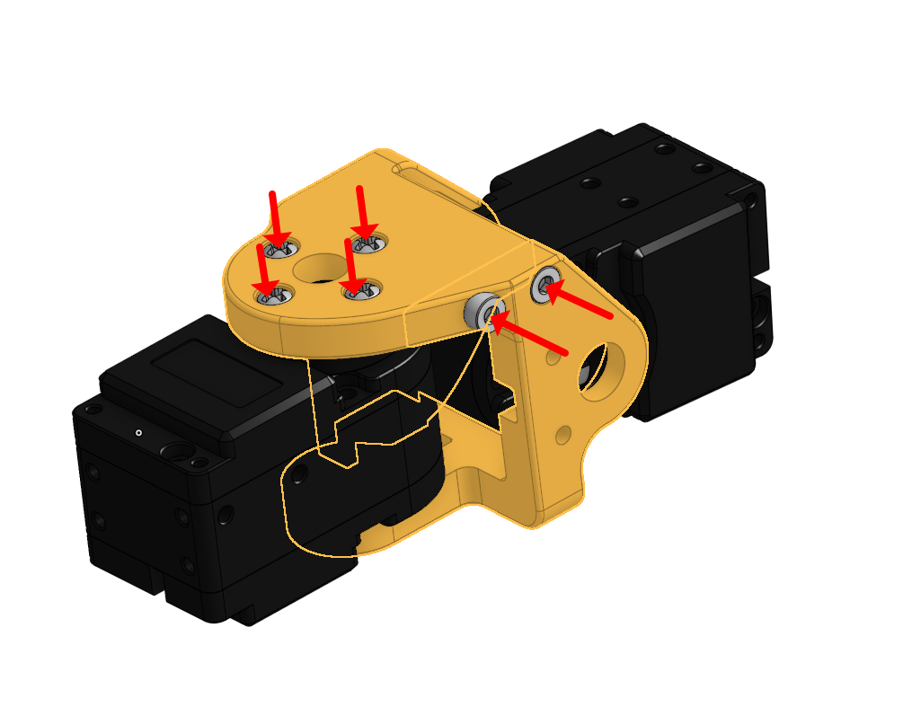
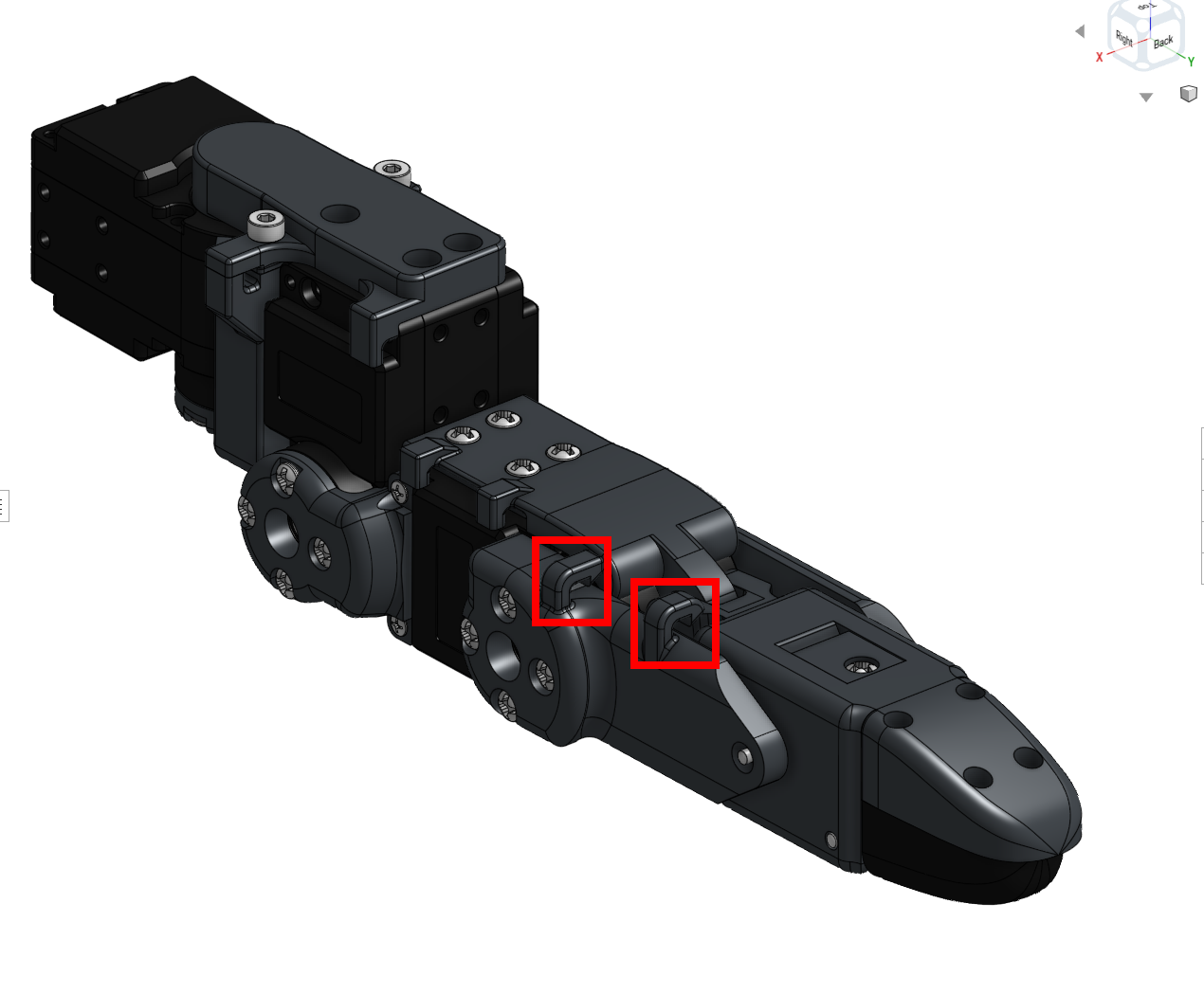
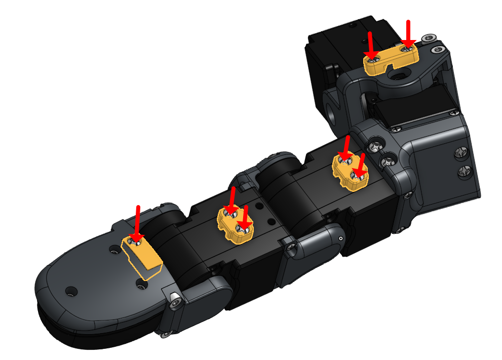
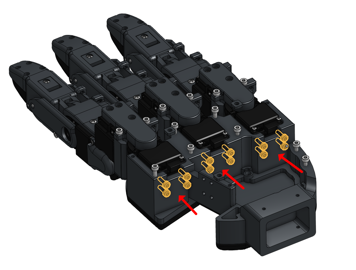
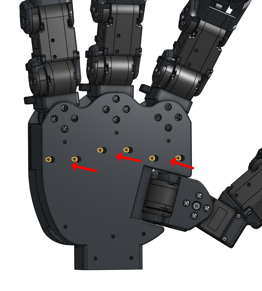
1. Attach the fully assembled finger to the palm at the specified screw points.
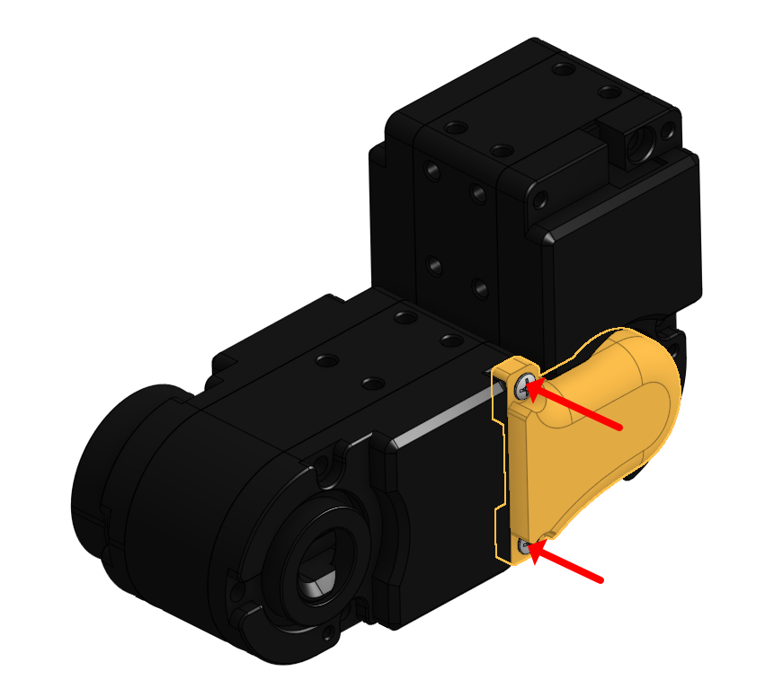
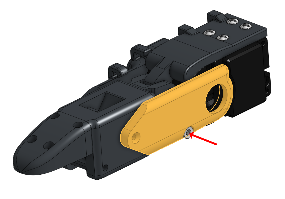
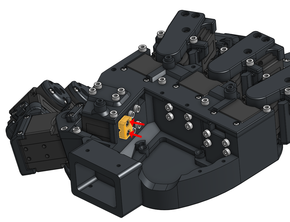
2. Anchor the thumb tactile wires by tightening one screw, checking for operational slack margin, and then tightening the second screw.
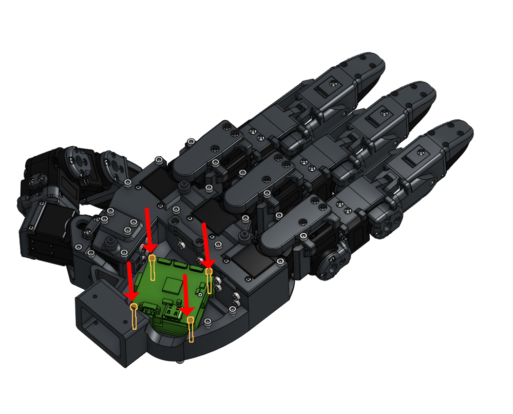
3. Align the two lower boards in the correct direction as shown in the reference image.
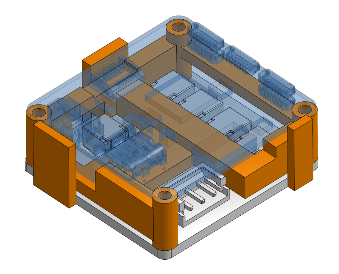
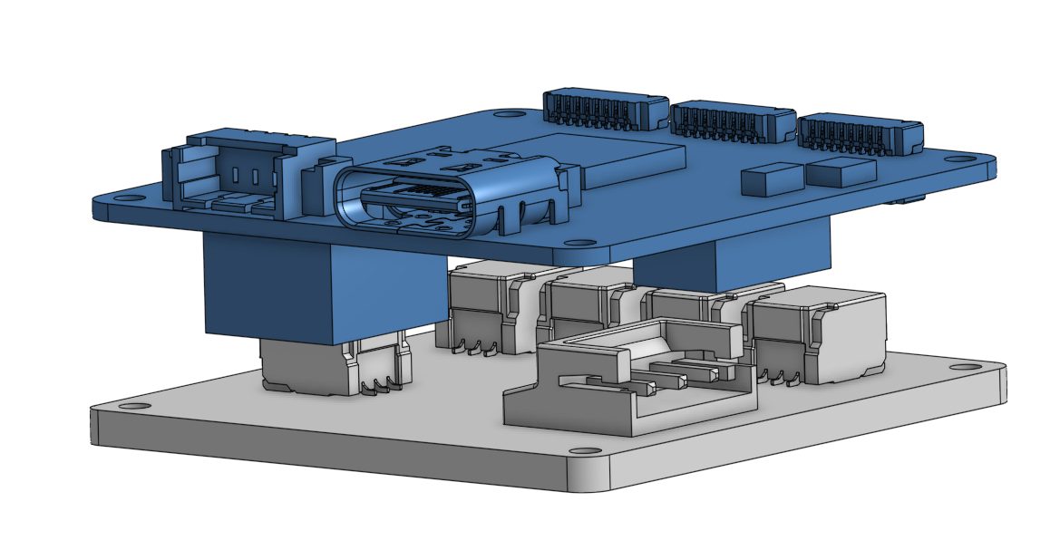
4. Insert four M1.6x16 screws to secure them.

5. Connect all required wires across the boards.
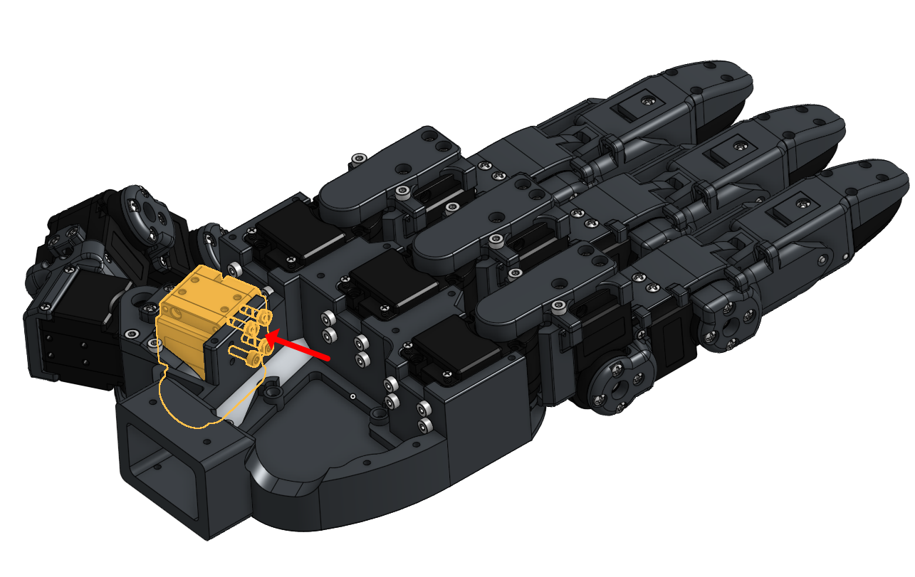
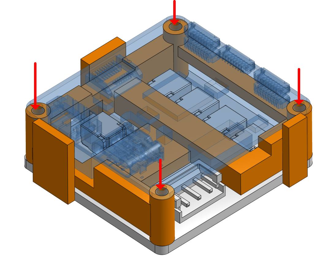
6. Use the corner guide to seat the board onto the palm, ensuring the Type-C connector faces downward.
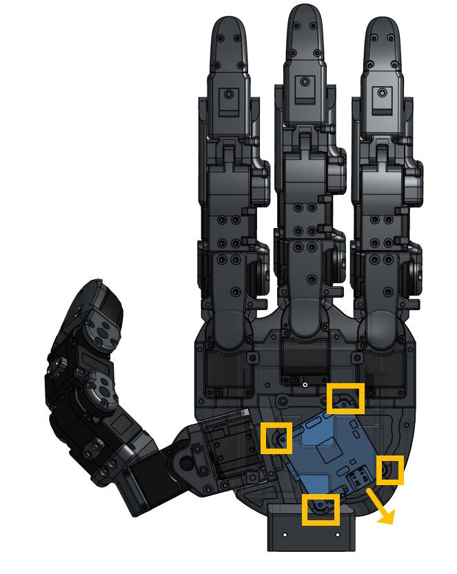
7. Tighten all board screws.
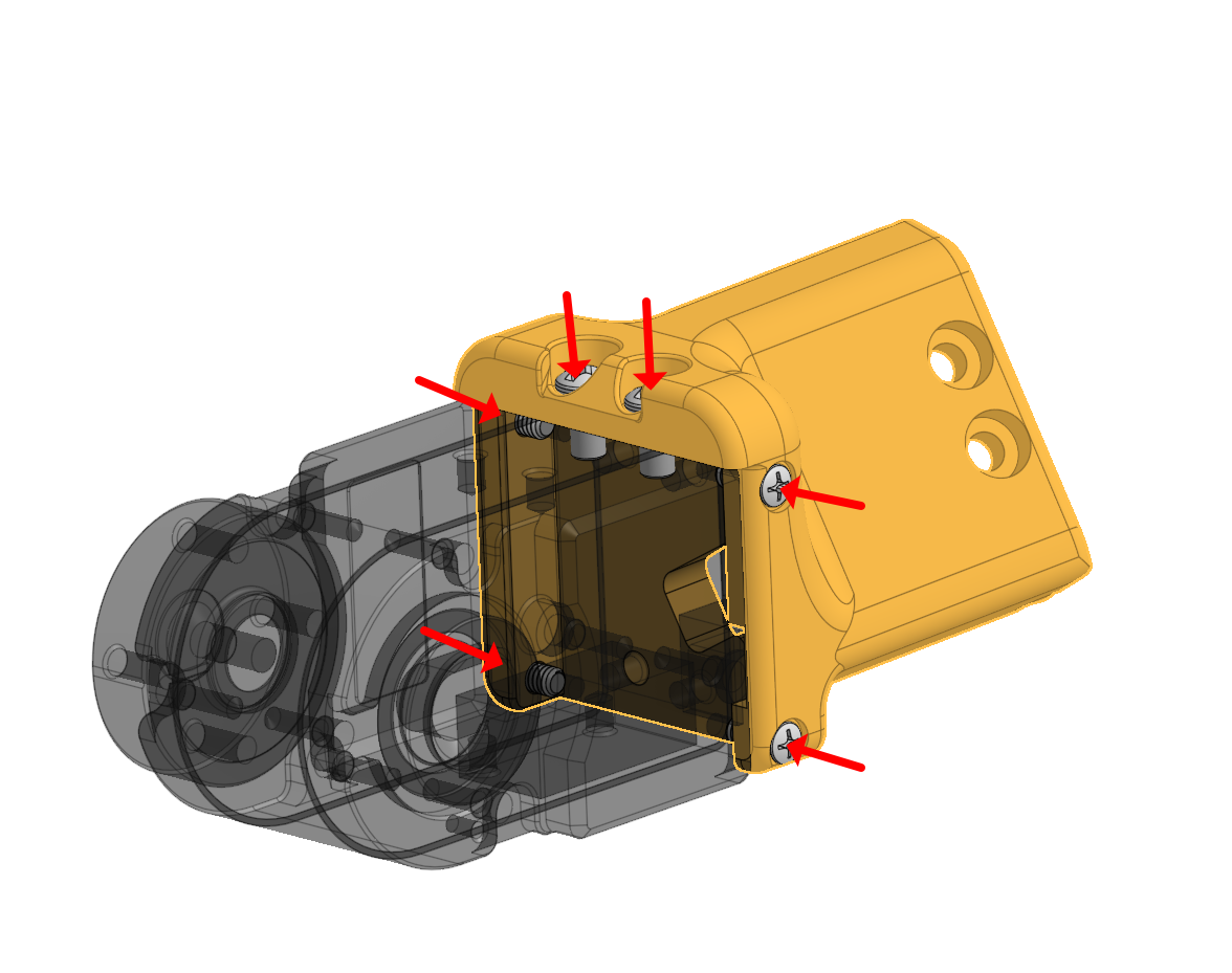
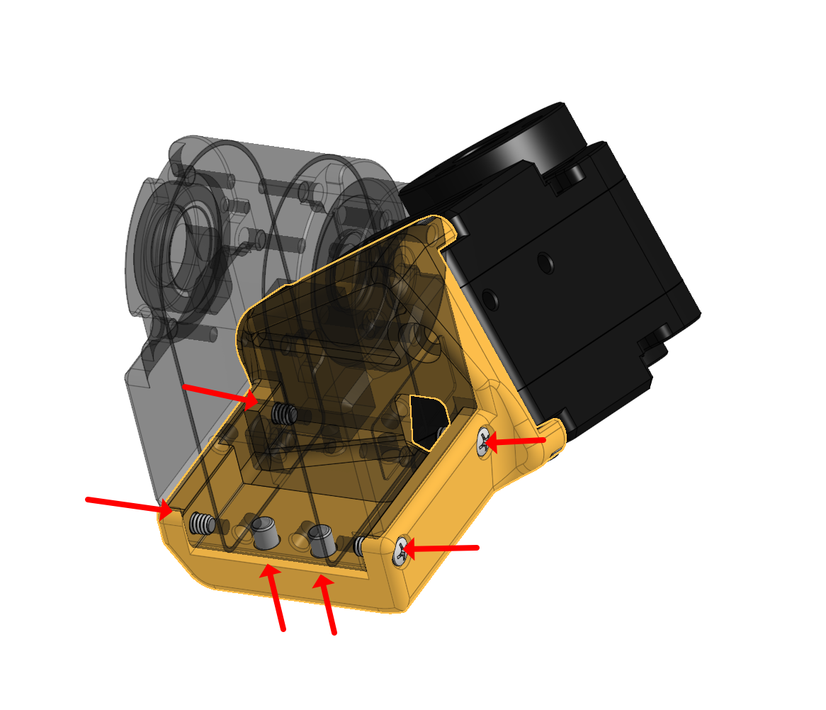
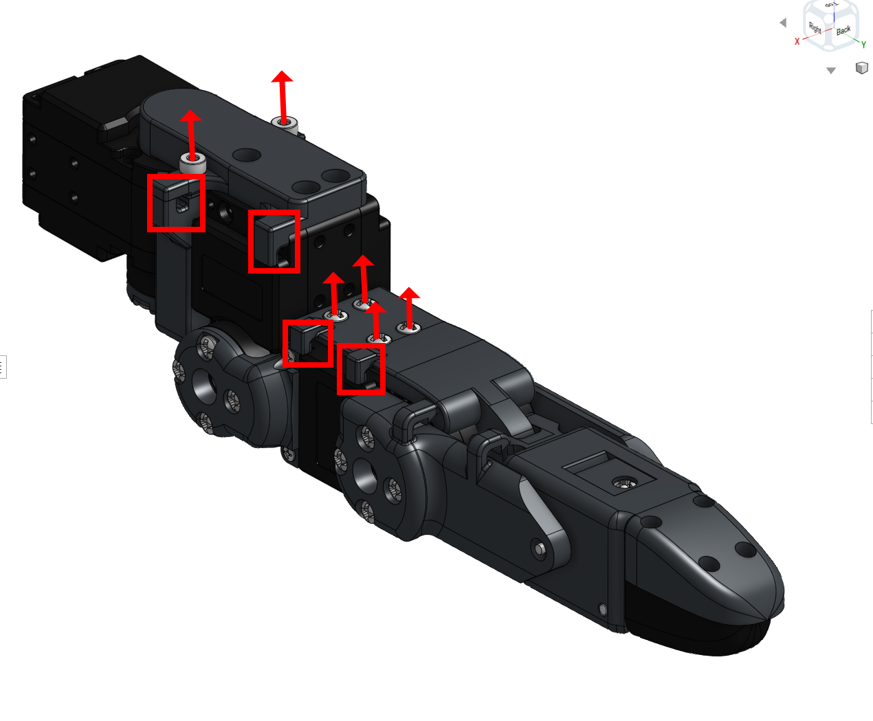
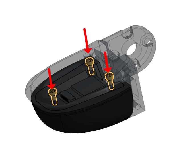
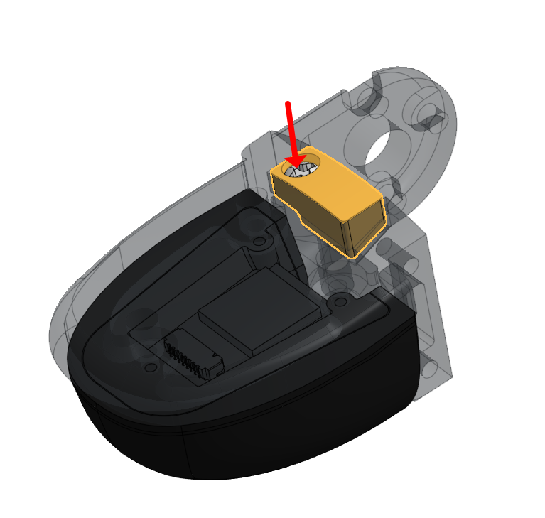
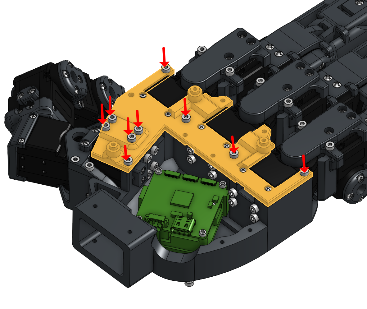
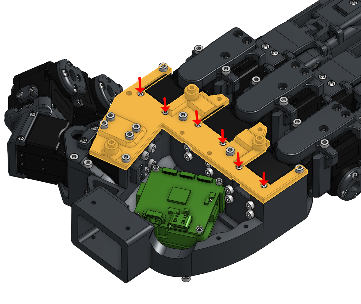
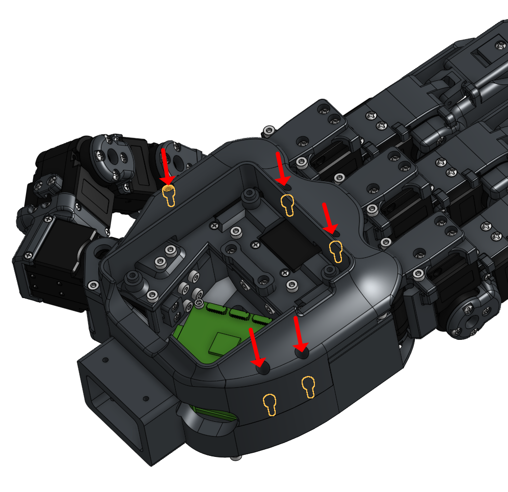
8. Anchor the Palm Top part onto the palm, being extremely careful not to pinch the Dynamixel wires from index and thumb
9. Double-check that all tactile wires are organized and have sufficient slack for full 4-DOF flexion and extension.
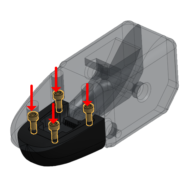
10. Close the cover, ensuring the tactile wires are routed as in the image above. Secure the cover by screwing in all M2x6 screws
11. Connect the main wire to the U2D2 power hub.
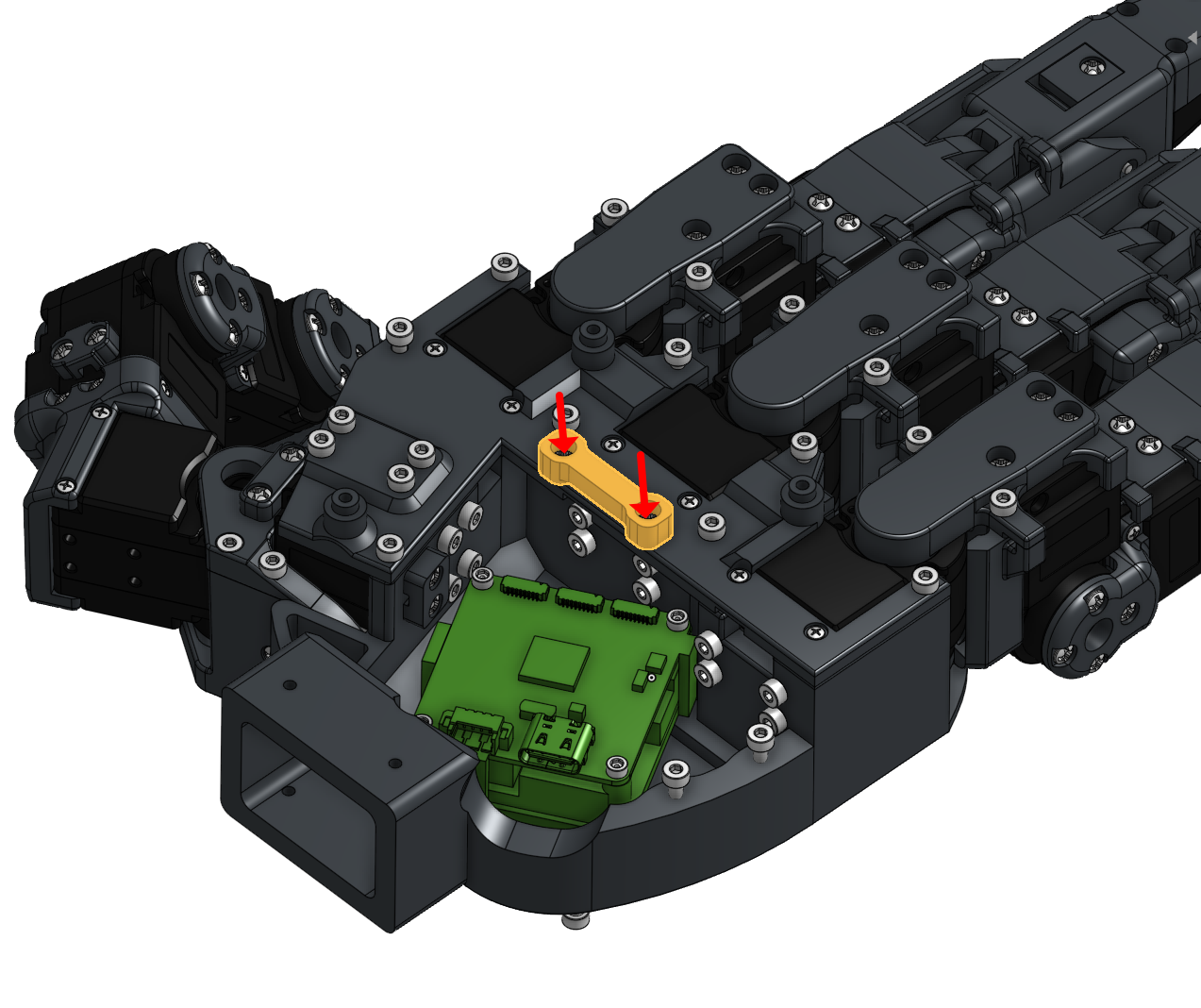
12. Place the U2D2 board onto the palm using the alignment holes.
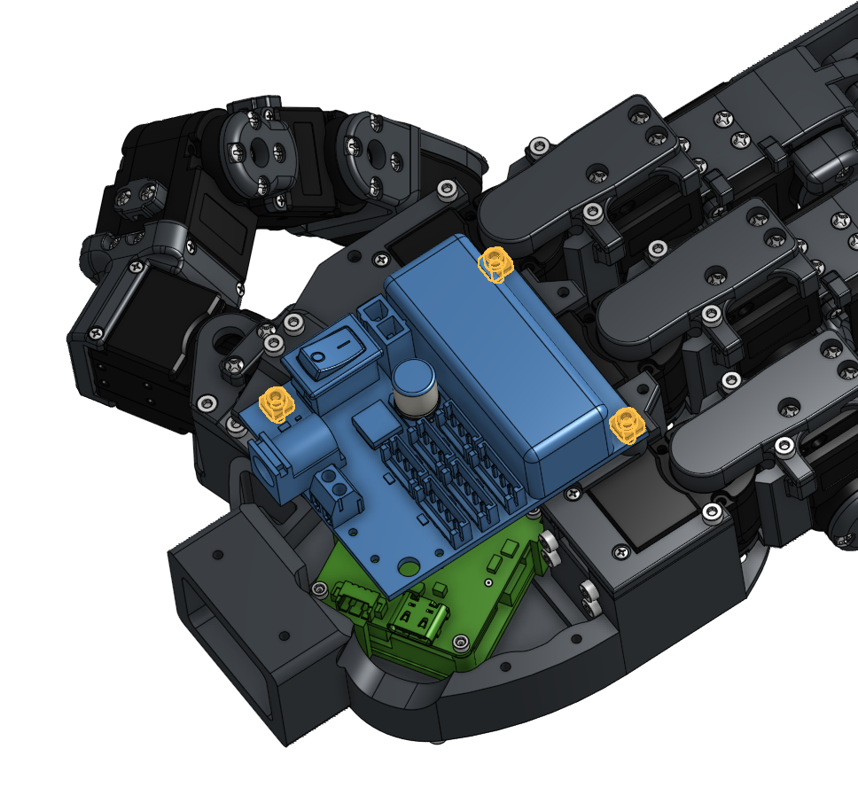
13. Secure the board using M2x6 screws and square spacers.
14. Close the cover cap, taking care not to trap any wires.
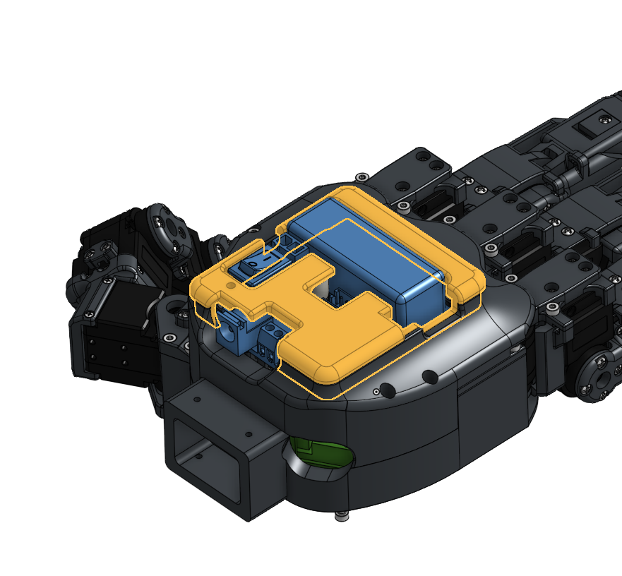
15. Fasten the TPU structure carefully; stop tightening as soon as the screw head is flush with the surface to avoid over-compression.